25+ block diagram automatic control system
Body Control Module BCM 17. Ignition Systems Control Honda Accord P0303 Meaning Causes Symptoms Fixes.

Top 25 Microservices Interview Questions And Answers
а - with an automatic transmission.

. Body Control Module BCM 14. Sound system amplifier control unit. Automatic Railway Gate Control System is a simple but very useful project which help is automatically opening and closing the railway gate upon detecting arrival or departure of the train.
The system for controlling temperature automatically is achieved by using. Rear axle electronic level control. Fuse box diagram.
Automatic Door Opening System Circuit. Honda check engine light code P0456 means Evaporative emission control system leak small. The main intention of this device is to maintain the engine speed constant by changing the steam supply to the engine.
Fuel System Control Module FSCM Gas except L96 or LU3 22. Stop Lamp Switch Electronic Brake Control Module EBCM Traction Control Switch. Fuse box diagram location and assignment of electrical fuses and relays for Mercedes-Benz E-Class E200 E220 E250 E300 E350 E400 E500 E63 W212.
According to this system there are two functional components in this project ie. Identifying and legend fuse box BMW 5 series 2010-2017. The first control system was invented by James Watts Flyball governor in the year 17.
Steering wheel heater control unit. Night vision system control unit. Steering column tube module control unit.
5 - see pos. 3 - fuse of the engine start circuit and ignition coils. Rear seat heater control unit.
Moisture sensor and motorwater pump. 23 An AVR LM92 Temperature Sensor System 25. Windshield Wiper Motor Module.
Click image to enlarge. 2 - the ignition switch. б - with a mechanical gear box.
Accelerometer weight scale hardwired signals etc and produces corresponding output depending on the nature of production and industry. 6 - the relay of. The circuit is built with an Arduino UNO 162 LCD PIR sensor connecting wires breadboard 1 k resistor power supply motor driver and DVD.
22 Block Diagram of a Temperature Control System using LM35 27. Programmable Logic Controllers continuously monitors the input values from various input sensing devices eg. Wastegate control solenoid or not used.
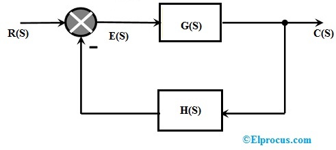
Additional 12V socket Or. The definition of a closed-loop control system according to the British Standard Institution is a control system possessing monitoring feedback the deviation signal formed as a result of this feedback being used to control the action of a final control element in such a way as to tend to reduce the deviation to zero. Fuel system control unit.
Automatic Door Opening System Circuit. The circuit connection of an automatic. Front passenger seat control unit.
A block diagram of a. Then motorwater pump supplies water to plants. Automatic temperature control system is an important application used in almost all modern gadgets and smart homes.
In its most basic form moisture sensor senses level of the soil moisture. Hyundai Elantra Wiring Diagram. The best examples of control systems are.
Transmission problems 2000 2001 2002. Process Flow Diagrams PFD are a graphical way of describing a process its constituent tasks and their sequence. The system displays the time taken by the train in crossing this distance from one pair to the other.
Center High Mounted Stop Lamp CHMSL 15. A PFD represents the process flow as it physically exists when walking the process A PFD helps with the brainstorming and. A typical block diagram of PLC consists of five parts namely.
Get FIXD for 1999. Schematic Circuit Diagram of Automatic Plant Watering Irrigation System. The installation is as shown in the block diagram.
1 - the block of the relay and safety locks in a motor compartment. Find out how to fix it in this article. 4 - rechargeable battery.
Bijan Elahi in Safety Risk Management for Medical Devices Second Edition 2022. Valid for transmission 722 724 725. 25 Block Diagram of an Automatic Temperature Control System using RZK 34.
Automatic transmission transmission mode button AIRMATIC. The circuit diagram of an automatic door opening and closing system is shown below. Automatic Transmission M99 MYC or MYD Evaporative Emission EVAP Canister Vent Solenoid Valve Transmission Control Module TCM M30.
274 276 278 642 651. Cruise Control Switch Steering Wheel SpeedPosition Sensor Power Take Off PTO 12. At present the control system plays an essential role in modern technology because these systems will affect our daily lifeless or more.
Fuse box diagram instrument panel fuse block 2007 Instrument panel left junction block. 14713 Process Flow Diagram.
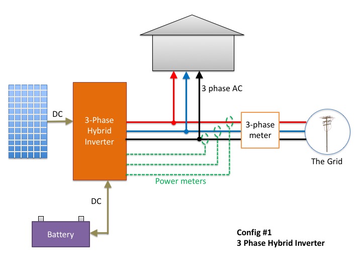
Don T Add Batteries To A 3 Phase Home Before Reading This
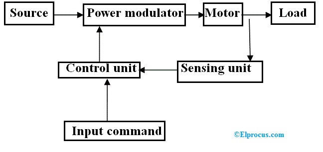
Electric Drive Types Block Diagram Classification And Its Applications

Resources Archive Zuken En
Safety Free Full Text Engineer Centred Design Factors And Methodological Approach For Maritime Autonomy Emergency Response Systems Html

Pin On Ph

Transferring Files Securely At The Foxtel Group Using Aws Transfer Family And Amazon Efs

Genogram A Pictorial Display Of A Person S Family Relationships Family Genogram Genogram Example Genogram Template
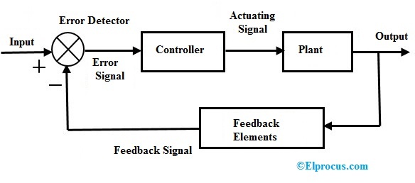
Closed Loop Control System Block Diagram Types Its Applications
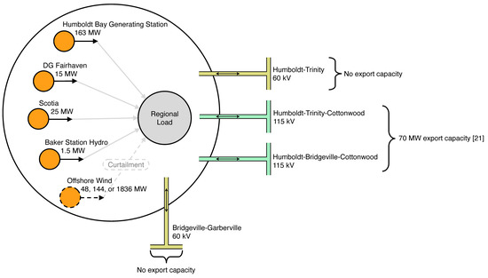
Energies Free Full Text Resource And Load Compatibility Assessment Of Wind Energy Offshore Of Humboldt County California Html
Closed Loop Control System Block Diagram Types Its Applications
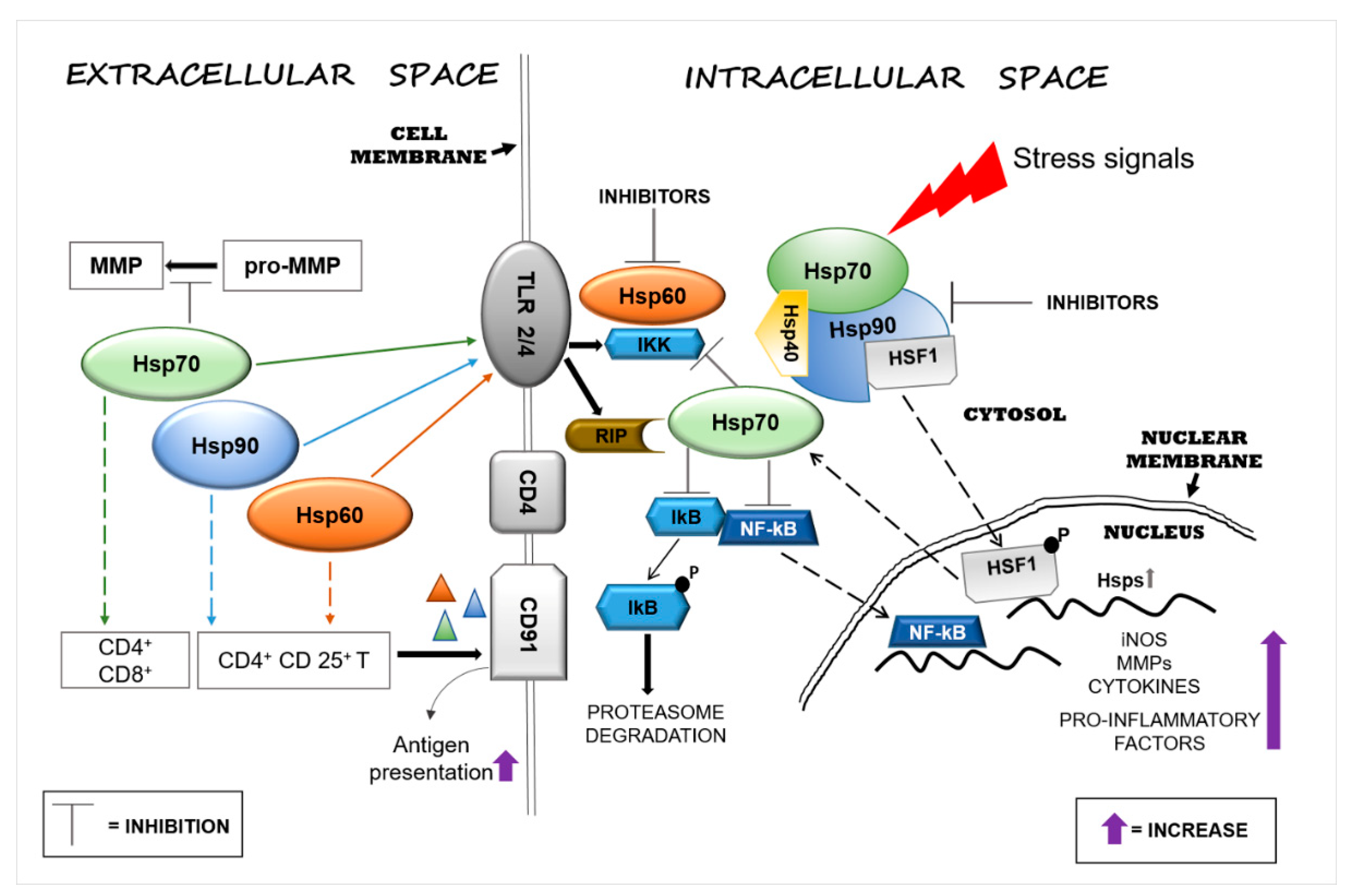
Applied Sciences Free Full Text Functions And Therapeutic Potential Of Extracellular Hsp60 Hsp70 And Hsp90 In Neuroinflammatory Disorders Html

Piezoelectric Sensor Pinout Working Datasheet Electronic Circuit Design Sensor Electronics Projects Diy
The Interceptor Aims To Fix Vulnerability In Millions Of Alarm Systems

Jenkins High Availability And Disaster Recovery On Aws Aws Devops Blog

Pin On Garden

Vnr0mjaikmwzqm
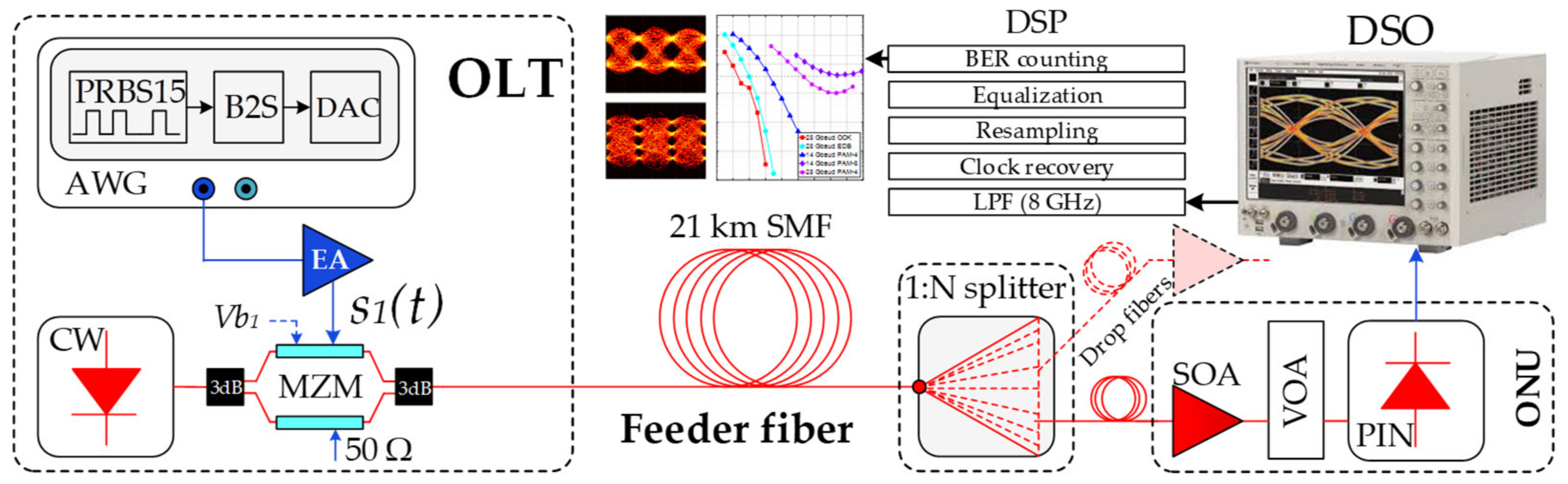
Applied Sciences Free Full Text Optical Power Budget Of 25 Gbps Im Dd Pon With Digital Signal Post Equalization Html